KleineBre's electro stuff
I used to be interested in electronics. I also used to fail to make just about anything work. Now that things are starting to make a bit more sense to me, here's the story of my progress.
2007-10-09 - First steps (how it all began)
 |
Somewhere in 2007, I felt an itch. I could program pretty well, but sometimes needed some hardware to solve a problem. And that hardware was invariably a full-blown PC. Sometimes, that's just too much. I wanted to learn to use microcontrollers.
So at the DND progathon 2007, I've invited Jeroen Domburg
(better known as Sprite from spritesmods.com). I have
been shown how to put bytes into an attiny2313
using avrdude and parallel cable.
I bought an experimenter PCB off him. It contained a relay, a 16x1 text display, 4 leds, 4 push buttons, an on-off switch and a buzzer.
Back home, I took the working experimenter board and wrote other LED blinking software. As I lost the backup that I made of the original ROM, I ended up losing pretty much all existing functionality of the board. I managed to make the LEDs blink differently though. |
Now that the blinking software was written, I tried my
luck at making some hardware to run this working software.
I failed. The 7805 fried, but even with a stable 5V supply
it never worked. Later on I found out I should probably
have connected two capacitors to the in- and out pins of
the 7805. Had I read the 7805 data sheet, I would
have known this, as it gives a typical example of how to
connect a 7805.
2009, August/september - Everything changes
Nothing happened for a while, but the itch remained. Then, at some point, I ran into a nice circuit simulator. In 48 hours time, I learned more about electronics than in several years before. I decided to give it another go and put together some hardware to run the blinking software. SUCCESS! The problem was not having a reset
button. (Pin 1+20 connected with a small capacitor
did the trick). Later on I found out the 'usual' way is to use a 10k resistor instead.
No longer having a parallel port on my computer, I
ordered a new, USB-based programmer. Being predominantly
a Linux guy and not having a lot of money to spend, the
one I settled for is a USBtinyISP. I didn't make it myself; I'd have needed a microcontroller programmer to make it work. To avoid this chicken-and-egg problem, I got mine on eBay.
2009-10-27 - My microcontroller programmer arrived
After over 2 weeks, my USBtinyISP finally arrived.
I must've been half-asleep when ordering it; it
came in all the way from Hong Kong, instead of the
US where I thought I ordered it (I didn't).
The postal strike here in the UK also mustn't have
helped.
I soldered together an elementary target board to
make sure it worked, using the pinout diagram on
evilmadscientist.com.
I skipped straight to "The next step is..." and got to work.
The minimal target board only took 6 wires and 1 IC socket. (Later
on I found out that in-system programming works exactly the same!)
The USB programmer worked perfectly! I managed to read and write hex files using
AVRdude.
However, I did order PCB head pins because just
6 loose wires is a bit flaky, even if it works.
2009-10-28 - Starting on a MIDI sender
One of the first projects I had in mind was
a little box that could send MIDI at the push of
a button. I found some MIDI code that supposedly uses the
built-in USART. Obviously that's better than
having the AVR manually toggling a pin, though
it should be able to do that, so I tried my
luck at programming the AVR with that code and
connecting it to my MIDI interface.
Well, the computer seemed to receive *something*
through the MIDI interface, but nothing sensible.
I suspected that the AVR was not running at the right clock speed.
I tried programming it once again but had the AVR
in the socket backwards (it got REALLY HOT!!!) but
it seems to have survived the abuse.
Apparently some of the non-working ASM code could
be attributed to interrupt vector table not being
defined. I tried C instead- if I'm using the USART,
I won't need to do bit clocking myself, after all.
I also found out that the clock most likely was indeed
at the wrong clock speed- By default, it should run at
about 1 MHz instead of 8. Apparently this could be configured by setting
the fuse values differently, eliminating a clock
divide by 8.
2009-10-29 - Fuse fuss
All right, so I set the fuses differently so
that the external crystal would be used as clock,
rather than the internal R/C oscillator. I found
appropriate values in the auto baud project at
spritesmods.com.
So, after figuring out how to use avrdude to
set the same values in the AVR, IT IS NO LONGER SEEN
by the USB programmer! I'm being told Wrong device ID, Yikes!
Did I blow up the AVR after all?
Apparently it's possible to get the AVR
back to work by feeding it a 1 MHz signal. But where do I get
one without any signal injector? Haven't got any
spare AVRs either. Then, in a moment of insight and
desperation, I try connecting an 8 MHz crystal to the target
board. The AVR is set to use an external clock,
after all- and it doesn't have one anymore, so
its clock is undefined. Perhaps 8 MHz is still
acceptable, but simply no longer divided by 8?
And my guess is correct: After hooking up the 8MHz crystal,
I can program the IC again!
I tried my luck at blinking a LED again, hopefully
this time at a more predictable speed. I started
a new demo program to replace the missing
firmware of the experimenter board yesterday,
and noticed that the pin connected to the buzzer
wasn't pin 13 but pin 8. That explains why I
didn't hear anything. After changing it to
pin 8, I managed to have the board generate a
beep again- AND to have a led light for 1/10
second, once per second. The pitch of the 500Hz
beep matched that of the 'beep' program on my
PC, so it does seem to be running at exactly
the expected clock rate of 8 MHz now.
Switching the IC around from one socket
to another all the time is already getting
annoying, though.
At this point, I've ran into some limitations
that I could have overcome more easily.
I really should get
- A few more ATtiny2313's to burn,
so I can make a few tools like pulse
generators etc
- More 8MHz xtals
- Prototyping board
- 220 ohm resistors for all my upcoming
MIDI projects
I'll probably take the experimenter
board apart pretty soon now and harvest
the components. But I've made some progress, at least!
Now that I've got output, I need to learn
to deal with input- and from that point
on I'll be able to do something useful!
2009-10-30 - Input, input, input
Processing input seems to work now- I
can read buttons and debounce in software.
It was pretty straightforward. Hooking up
a button to ground and an input pin works
well enough. I read a tip saying that using #defines to
configure which pin is the button pin and
which port is the button port is a good
idea; it makes things more easily
configurable, and when working in C it will
make porting across different AVRs easier.
For the sake of my MIDI project,
I've also made sure that I can use the button
as a toggle- pushing it once gives a beep,
pushing it again gives another beep. To
make the automatic MIDI track arming device
work, all I need to do now is send out
commands to the serial port of the chip.
And I believe I have some working code for
that.
Saturday 2009-10-31 - Contact!
I went to get some 220 ohm resistors at the
shop, then set out to work.
It was a bit fiddly, as at some point
things weren't working, period-
and I wasn't sure whether the problem was
software or hardware.
I combined the example code in the data
sheet with the MIDI code that I had,
so that -to the best of my knowledge-
it should work, then started blaming
the hardware. Just having 1 signal and
1 ground wire didn't work at all, at
any time- so I added the second wire
with 220 ohm resistor hooked to +V.
That still didn't work, so I assumed
I swapped around pin 4 and 5 (as implied
by the author of the other MIDI code).
Well, thanks for the suggestion-
that did the trick, and bytes started arriving at my
computer. People drawing pinouts should really
specify which side of the plug you're
looking at!
After plugging in the midi sender
to the HD24, it also worked like a
charm. Asked for comments on the mailing
list. I'd soon grow to regret that :)
2009-11-01 Sunday, Documenting day.
Comments are starting to trickle in;
some suggesting that a status LED would
be nice, others suggested tamper proofing
the box.
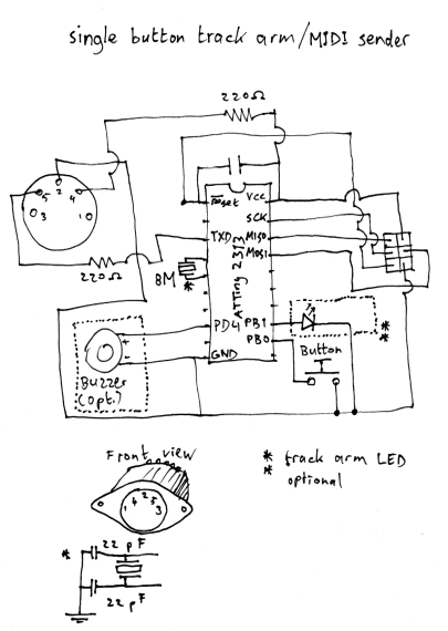
I added an LED to the schematic and
dubbed the project 'complete'. Following tradition,
I used Advanced Schematic Drawing Tool to draw out the
schematic (pen and paper):
Still haven't decided how to power it
from the HD24.
2009-11-02 Monday - A bloated feeling
The device has a beeper attached to it
which will soon go. Until then, I've
been playing around with making beeps
at predictable pitches. So far, the highest
pitched beep that I've made was 500 Hz;
due to the fact that delayms only takes
whole milliseconds. But I found out that the
delay library also contains a function
_delay_us.
I cut out most of the midisender code,
used _delay_us instead of delayms, and...
found out that the code was too large to
fit in the ATtiny2313 anymore. WTF?
As it turns out, _delay_us and _delay_ms must
be called with values known in compile time,
otherwise a lot of bloat is added. Ah, that
explains the extra definition of the delayms
function in code, which just calls _delay_ms(1)
several times. Didn't seem very accurate to me
though. However, it is possible to call
_delay_ms with a double, not just with integers.
I can make higher pitches after all!
So, I managed to play a scale. Tried Pulse
Width modulation next to simulate volume.
Well, it sounded very cool (a chorus-like effect)
but didn't seem to emulate volume. Maybe the buzzer simply
keeps up; or maybe I've just got it all wrong.
I'll have to figure out which another time.
People seem interested in the MIDIsender
project. Maybe I should go one step more
pro and order in my PCBs rather than etching
my own or using prototyping board.
So I tried some CAD software to draw a PCB.
Whoever wrote it should read the section
on intuitive user interfaces from my book
'Growing Better Software'. How do you
delete something? You select it, you hit
the delete button.
Instead, this programmer decided that it
was a good idea to implement deleting as
ctrl-shift-dragging around the item to
delete. Seriously. An hour and a half to
learn to place 5 components on a circuit
board is too long. I'm dropping this piece
of crap software which shall remain nameless
for now.
2009-11-03 Tuesday - Back to basics
More suggestions coming in to power the
device. Some suggest leaving out the
'unarm all tracks' command, which is
automatically done by the HD24 once swapping
song anyway. This would solve the tamper
proofing. Also, the LED could simply be
left out then. Oh, and if the button is
moved to interrupt the power supply, then
the whole device can simply be battery
powered, because 99.9999% of the time the
button is not being pressed.
Brilliant simplicity, but I'll have to
redesign part of the midisender.
I was recommended 'Eagle' PCB designing
software by an old friend. Didn't manage
a full circuit board yet, but it's by
FAR the best program I've ran into so
far. And it runs on Linux too!
It's still slower than drawing schematics
by hand, and I haven't got the hang
of it quite yet- but it's definitely
more friendly than what I tried before.
This is going to work.
2009-11-04 Wednesday
More suggestions. Have I thought of
arming 48 tracks? Or more? Someone
came up with a MIDI command that the BRC
sends to arm 48 tracks. It has enough
padding zeroes at the end to allow for
arming 128 tracks- all the ADAT standard
supports. I'll be sending this new 'arm
128 tracks' command instead then.
So now the whole MIDIsender is obsolete,
both in software and hardware :)
2009-11-05 - No scope
Even though I've pretty much decided
on a battery powered MIDIsender box now,
The 'how to power the device' spawned
another interesting discussion about the
pinout of the sync port of the HD24.
Someone posted the official pairing
of the pins, so I suggested someone look
at those pairs of pins with a scope- and
Alan G did! As a result, we now we have
more of an official spec of the ADAT sync
port than we ever had before.
I also received some additional techdocs
regarding SysEx that the ADAT M20 supports,
and that the HD24 might support.
Meanwhile that old friend (Bernard)
wants to get me to do USB- creepy stuff!
Also, thanks for sending out the IrDA
components! I'm sure I'll be doing some
remote and/or USB stuff very soon!
Haven't got a scope myself. Suggestions?
2009-11-06 Friday
I ordered in more ATtiny2313s so I'll have
components to build several MIDI senders.
Thought I'd still have to drop by at the
Maplin for 7805's, then changed my mind;
I could just use 220 ohm resistors as
voltage divider and power the uC with 4.5
volts. Not the most efficient solution,
but quite cost effective. Two resistors
are cheaper, more foolproof (can't
accidentally mess up the orientation),
less trouble to solder and probably last
longer than a 7805+2 capacitors; and using a 7805 to
go from 9->5 volts isn't very efficient
either anyway. Not that it matters much
if the device is switched off most of the time.
Asked Xavier about his Gordius/FCB1010
project and realised that I now had the
knowledge to add MIDI-out to my guitar
effects processor, a Digitech RP7.
The actual pedals should be simple enough:
Just hook up a fairly large resistor
to them and steal a small current.
This small current could then be used
to switch a transistor hooked up to an
ATtiny which then could send out MIDI
(program change messages for example).
It sounds like a <10 pounds job which could
save me the money for a 110 pounds
FCB1010, and it will look just as good.
I wonder how tricky it is to do the volume
pedal as well.
Oh, and I've been thinking about my
hexaphonic guitar project, which has been
on my mind for a while. With all this
talk about serial communications,
I started thinking whether I should just
heavily filter the guitar strings and
output square waves as serial data.
If I'd encode each string as 1 bit
and capture only the base frequency,
115200 bps would be more than enough
for all strings. And a regular jack
cable should do fine to transport this,
right?
2009-11-06 - Opening up the pedal
I've taken apart my RP-7. Four of the
pedals sit on their own daughterboard, so those
should be easy to mod. The volume pedal is done
optically- clever solution, as it will never
crackle. However, the obvious place to mount a
MIDI port is already occupied by a large
capacitor. It should be possible to move it
away though. For now, I've closed up the pedal
again; it seems a doable project, but I'll
have to think over if I want to do anything
with the remaining pedals.
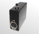
Sunday 2009-11-08 - The shiny black box
I've redesigned and re-built the MIDI sender. It
is now battery-powered and built into a pretty
platic box. It hardly fit; I underestimated the
size of the PCB. The LED has disappeared. So has
the buzzer. It's no longer on/off- only an 'arm
all tracks' command exists now. Which arms as
many as 128 tracks. No more track unarming, so
no tamper-proofing is needed. And because it only
sends 1 command, it doesn't need to save state, so it
can be powered off almost all the time- just like a
TV remote control. Oh, and the 6 pin ISP header isn't
necessary anymore as it's just for prototyping.
Less is more.
I've asked for comments about the schematic. Guess what- it was all wrong. The voltage divider should have been a 7805 with 2 capacitors. I should have used two 22pF capacitors with the crystal. Should have mounted a 100nF capacitor between VCC and GND. And the capacitor between VCC and RESET should really have been a 10k resistor. A diode to protect it from reversed batteries would also be a good idea. All right, lessons learned. That's why I asked. The production version will be completely robust!
Wednesday 2009-11-11 - The powerful remote
I don't know who knocked the remote control of the
media box into the sink, but it's been soaking in
there for a while. Dried it up best I could, by
shaking it first, then putting it on the heater all
day. Nothing.
So I opened it up. Something
on the PCB looked suspiciously like programming pins.
And indeed, there's a microcontroller in there.
Motorola. 32kb Flash. For a remote control. I wonder
what else one could let a remote do? Anyway, cleaned
off the rust and sprayed it with contact cleaner.
that did the trick; it works again now.
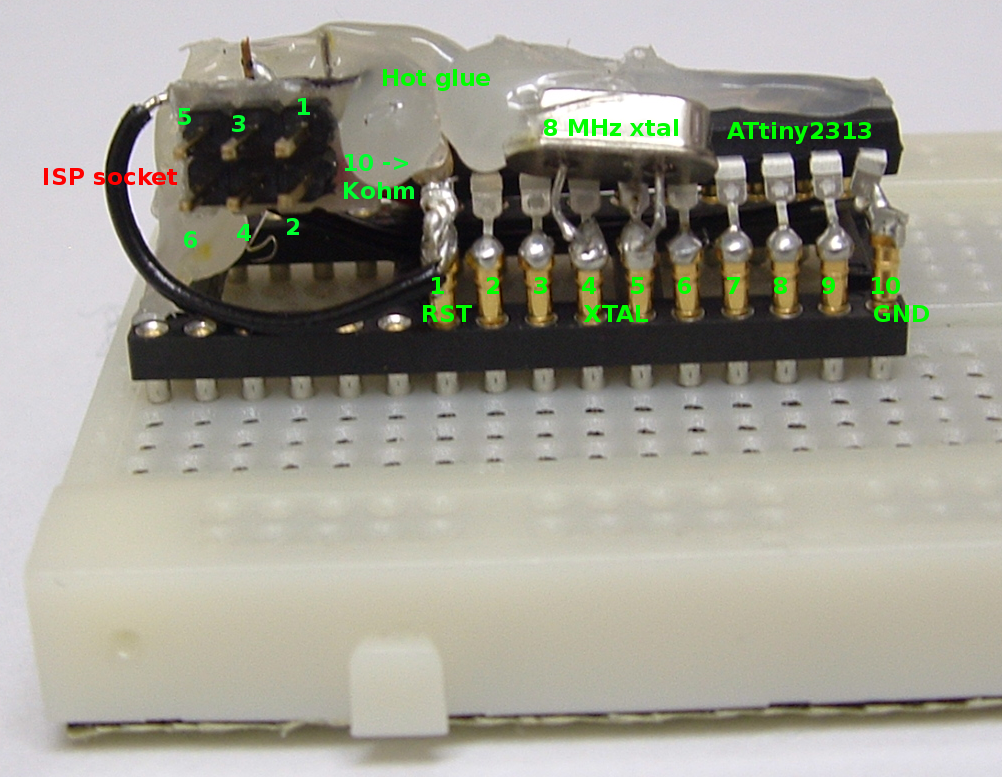
Wednesday 2009-11-11 - The breadboard header
I've run out of prototyping board, so I wanted to find a
way to use the 6-pin ISP header with a breadboard. Inspired
by a similar project, I soldered an ATtiny2313 onto a much
bigger IC socket, and mounted reset resistor, 6-pin ISP
header and crystal on there as well. To hold things in place,
I've used generous amounts of hot glue. It's ugly as hell,
but hey- it works. It definitely will help me speed up
prototyping, too, as I don't have to solder everything
in place anymore.
I've taken the time to unsolder the text display from the
experimenter board. Tough call without desoldering equipment.
I figured I'd just find the data sheet for it and that would
do the trick. Bad luck- there seems to be no documentation at
all about this display. I've described the display to the
el101 group, and they suggested I look up the data sheet of
the controller IC, then measure the 14 pins of the display
against those of the controller. That gave me a semi-official
pinout for the display.
As it turned out, that pinout was similar to many common
16x1 text displays.
Wednesday afternoon 2009-11-11 - The display displays.
After messing about pressing the display into the breadboard
(it doesn't fit!) I wired up its 10 relevant pins (the other
4 are only needed in 8-bit mode; I'm running in 4-bit mode).
It still only shows black. Duh- until I added a potmeter for
contrast. That made it much more readable.
As it turns out, others already wrote an LCD library for a
similar display. I needed to configure a few things, but overall
this thing 'just works'. A day well spent.
Saturday 2009-11-14 - Stepper motors and USB
After last weekend, I decided that stepper motors and USB
were two fields that still needed some attention. I also
could use to have the means to create my own PCBs again.
Wouldn't it be great if I could just plot PCB layouts straight
onto copper with candle wax or something?
So I begged for
a floppy drive and got a reply.
As for the USB stuff, that's a bit tricky. After all, I've
got a bag full of 8MHz crystals but need 12 MHz for USB.
And of course, now that I'm going to run at 12 MHz, I find out
I just soldered an 8 MHz crystal onto my ISP header
socket.
I also lacked the right resistors and diodes. Drat. Of course
there's that wireless keyboard/mouse combo that I got for free
on Freecycle. Now that I'm running the Mac and PC through Synergy,
I'm not using it. Perhaps I'll want to again at some point...
Ah, what the heck, let's open up the receiver and take a look.
AHA! A 12 MHz crystal, just what I need. And *snip* the cable
goes too. I've soldered the 8 Mhz crystal off of the header
socket, and marked the crystal pins red. I can now swap around
between 8 and 12 MHz by just plugging a different crystal into
my breadboard.
Sunday, 2009-11-15
I picked up a nice old 5.25 drive with a big stepper motor.
I wonder if I can find another so that I've got similar motors
for each axis. A guy in Holland still seems to have a spare
one; or perhaps I can just turn my old printer (which I got
on Freecycle) into a plotter. It sure has a nice gear belt,
and it might be a more useful destination than 'to make music'
which is what I originally planned.
I also dropped by at the electro store for diodes
and resistors. I bought a nice baggie of euro values resistors-
that should give me the right resistors for some time to come.
I've reorganized my components box so that they're easy to find too.
I also bought all the 1N4148 diodes that they had in stock
(both of them)- makes you wonder how they manage to keep a store open.
Didn't manage to get the USB device working yet,
though.
Tuesday, 2009-11-17 - Partial USB success?
As I had a day off, I continued on my USB device. First of
all, I needed more debugging info, so I hooked up a few extra
LEDs to the circuit board and made them blink several status
messages. I also added such status blink messages in code
to the various interrupts/events that can apparently occur.
This gave me more information in an unexpected way: Whenever
I'd query the connected USB devices with lsusb, the
device would still not show up, but the LEDs would blink.
This meant that there was probably more logging information
available in the system log. And yes, after typing dmesg
I could see that a USB device was indeed detected (or so I
thought):
[12522.152428] usb 3-1: new low speed USB device using ohci_hcd and address 95
[12522.329377] usb 3-1: device descriptor read/64, error -62
[12522.607298] usb 3-1: device descriptor read/64, error -62
[12522.880220] usb 3-1: new low speed USB device using ohci_hcd and address 96
[12523.057168] usb 3-1: device descriptor read/64, error -62
[12523.335089] usb 3-1: device descriptor read/64, error -62
[12523.608011] usb 3-1: new low speed USB device using ohci_hcd and address 97
[12524.009897] usb 3-1: device not accepting address 97, error -62
[12524.182847] usb 3-1: new low speed USB device using ohci_hcd and address 98
[12524.584731] usb 3-1: device not accepting address 98, error -62
In a forum, someone mentioned that this probably means enumeration fails (that much I had figured out already!). A cause was mentioned too: 'All pins must
be configured as input with no internal pull up resistor'. I had the
pins configured as output pins, so I changed that, to no avail. In
case the blink delay was causing trouble, I disabled that, too; but
it didn't make a difference. What else could be wrong?
Well, pretty much everything. Apparently the error 'device not
accepting address' means that the pull-up resistor is detected, but
not necessarily anything else.
Clock speed, zener diodes and I/O setting of pins can be wrong.
Zener diodes? That's new- Some of the schematics I've seen used
1N4148 or 1N4001 (not zeners).
Assuming that "I'm doing it wrong", for relevance, I'll stick
with a circuit that I know works right
on the controller that I'm using. That is, the USBtinyISP circuit
for the ATtiny2313. I may live to regret it, as almost all flash
is taken by the USB library then. In any case, I ordered in some
3.6 zener diodes. Also, in a forum discussion I've seen someone
solve his USB trouble by following proper electronics practices,
so I'll probably go as picky as I can on the next version of the
hardware...
Thursday, 2009-11-19 - Partial USB success!
It is no longer a question - I've had partial success creating
my first USB device. The zener diodes arrived, and as planned,
I've followed the (USB part of) the schematics of the USBtinyISP
circuit. To be fair, they're the 'wrong' diodes; as I could not
find the exact part number, I settled for other 3.6V 0.5 W zeners
hoping that that doesn't make too much of a difference. I hooked
up the device on a breadboard, and also made sure to add the 3
extra LEDs, as last time they added a lot of value for trouble-
shooting. I also connected a button like last time, but it had
to move to another pin as pin 11 was now in use. I made sure
that a capacitor was between Ground and VCC. Then, recalling
what I had learned last time, I made sure that
- The pins were set to input without pull-up
- The file usbconfig.h used the right pins
After flashing this to the ATtiny and hooking it up,
it flashed the initial LED testing sequence (to show all
LEDS work). The LEDs then showed off, on, off- which stood
for status code 2. Upon inspection, that was the code set in
the USB read event- The computer was trying to read from the
device. As the device still didn't give any response,
I still got the error device not accepting address, however
I now knew where things got stuck. I replaced the USB read code
with a dummy read routine, and PRESTO! After typing lsusb,
the device shows up in the device list as 'USB Design by Example'.
Now, I should make it actually do something.
Friday, 2009-11-20 - Time for a break
Well, it's still not working. Obviously I need to read up
on the protocols and technical documentation to get this to
work. Movie night tonight and I'm feeling like doing something
a bit less serious, so I'll save this for later.
Saturday, 2009-11-21 - Pulsating LED
I decided to do something simple today: a blinking LED.
Actually, a pulsating LED: a LED that gradually comes on,
then gradually fades out again. As the human eye is pretty
slow (it perceives 25 frames per second as movement), blinking
a LED much faster will make it seem lit constantly. Depending on
how much of the time it is lit, it will seem brighter or dimmer.
To complicate things further, I wanted the code to be interrupt
driven- so that it could run as a background process, because
such knowledge will be useful for future projects.
Anyway,
it works. Hooking up a beeper to the LED output sounds pretty
interesting too. Perhaps I'll build a minimal MIDI synth?
Wednesday, 2009-11-25 - Reading a resistive keypad
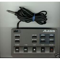 |
I'd like to be able to interface the Alesis LRC with my PC- without modifying either. This Alesis LRC is an analog, wired remote control. Take a look at the jack plug: It's a mono plug. It's unpowered. It is nothing more but a resistor network, varying from 75 to 1408 ohms (1408 meaning 'no key pressed'). The 'play' button can be used in conjunction with some of the other keys (FFWD, REW), giving for a total of 18 valid states (including 'no key pressed').
I've been trying to hook up this keypad to the one model microcontroller that I have available at the moment: an ATtiny2313. It proved to be a bit bumpy ride, because the ATtiny2313 does not have a built-in Analog-to-Digital Converter (ADC).
|
I've found a document online, though, that describes how to do A/D conversion with an ATtiny2313 or similar AVR. It works by repeatedly charging and uncharging a capacitor, and timing how long it takes to charge. This is similar to how analog joysticks used to work on the original IBM PC. I've tried my luck at it, but unfortunately the code that came with the document is in assembly rather than C. As I don't like wasting time, I used Google to search for a possible C port of the code. Nothing. Asked on the AVR forum if anyone had found anything; the short answer is 'no'.
I tried my luck at my own port, and put together my
own design for this purpose- but it didn't work too well, and neither did any of the following incarnations. At its best, I was even getting readings; but they were all over the place. It looked like I had more noise than signal, possibly caused by the fact that the capacitor had to be ridicilously small. I'm not sure why I got so much noise, but my best guess so far is that the strips of the breadboard may have had sufficient capacitance to mess things up.
Perhaps I should simply use an ATtiny45 for this?
Friday 2009-11-27 - Improved designs
All right, so I had a little bit of time today. I soldered together another
iteration of the MIDI sender button. This time, on Veroboard/strip board, because I still don't have the means back together to etch my own PCBs. Unfortunately, using Veroboard ruled out using Eagle (or pretty much anything else), so I just went with the flow. I must say, I'm a bit surprised, as it gave for a bit neater layout than using matrix board, and a bit smaller as well. I've also improved the design a little bit; This one doesn't use a voltage divider but a 7805 (which automatically accounts for having a capacitor between the VCC and ground pins of the IC). I guess I'll have to document this version soon.
In the meantime, someone on the electro forum suggested I hook up the
analog remote control to the microcontroller using a pull-up resistor of
about 1k to the VCC line. He included a spreadsheet showing the voltages
that I'd be able to expect. Hey- suddenly the range seems more usable,
as it goes from ~.35 volts to ~2.25 volts. What is more important- I get it, because
the pull-up in combination with the LRC is simply a voltage divider. I looked for a more optimal pull-up value, but didn't find any. Either the range would
be smaller, or the smallest ADC step. Currently, on an 8-bit ADC the measurements for different buttons would be as little as 5 values apart; this implies that a 6-bit ADC will, in fact, most likely not suffice. I've also been pointed to a document showing how to use op-amps to scale voltage ranges to other voltage ranges.
So, it still doesn't work. But the good news is, that it sounds increasingly likely that it will. By using the 10-bit ADC of an ATtiny45 with 1k pull-up and possibly an op-amp to extend the range, I've got 3 powerful tools which make it likely that I'll get useable readings next time.
Saturday 2008-11-28 - Instant MIDI sending interface
To speed up development of my MIDI based microcontroller-projects, I've
put together a little gadget which I call my 'instant MIDI interface'.
It's essentially a DIN plug with 2 resistors and 3 wires attached to it.
(In this case, the DIN plug is a 7 pin plug which I accidentally bought
instead of a 5-pin plug. MIDI cables plug into it just fine though).
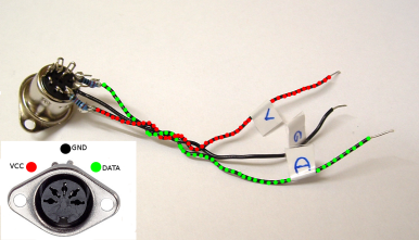
(Click to show full-size) | I've labeled the wires D, V and G for Data, VCC and Ground. The resistors on the Data and VCC lines are 220 ohm as per the MIDI spec. VCC is assumed to be 5 volts. All we need to do now to finish the hardware, is to connect the three wires to the appropriate pins of the microcontroller. If you're using an ATtiny2313 like I do, G goes to GND (pin 10); V goes to VCC (pin 20) and D goes to pin 3, which is Tx (USART output). |
I hook the whole thing up to a 8 MHz crystal, then set the fuses to use
an external clock:
avrdude -c usbtiny -p t2313 -U lfuse:w:0xff:m
avrdude -c usbtiny -p t2313 -U hfuse:w:0xdf:m
With all hardware set up, finally it's time for a bit of code:
#define F_CPU 8000000UL
unsigned int baud=15; /* based on 8MHz clock; 8000000/(8*(15+1))=31250 */
/* use 23 for 12 MHz xtal */

void USART_Init()
{
  /* Set baud rate */
  UBRRH = (unsigned char)(baud>>8);
  UBRRL = (unsigned char)baud;
  /* Enable transmitter, not receiver */
  UCSRB = (0<<RXEN)|(1<<TXEN);
  /* Set frame format */
  UCSRC = (0<<UMSEL)|(0<<UPM0)|(0<<UPM1)|(0<<USBS)|(1<<UCSZ1)|(1<<UCSZ0)|(0<<UCPOL);
}

void USART_Transmit( unsigned char data )
{
  /* Wait for empty transmit buffer */
  while ( !( UCSRA & (1<<UDRE)) )
       ;
  /* Put data into buffer, sends the data */
  UDR = data;
}
... and that concludes our MIDI sending interface.
Saturday 2009-11-27 - Mega trouble
As my ATmega8 controllers have arrived, I decided to give it a try and
put together my LRC decoder. First of all, I put together a minimal target
board on breadboard, using the description that previously served me well. I then ran into some fuse trouble, figured out what the right values were supposed to be, and used those to make it use the external clock. I'll have to get back to the
other uC (which has incorrect fuses and is not programmable now) and fix the
fuses some other time.
I hooked up the 'instant MIDI interface' (see last week), built the MIDI sender code, and voilá! MIDI started arriving at my PC. So far so good, I thought.
However, the Makefile was still set to compile for ATtiny2313. I could therefore not use the ADC of the ATmega8. "Simple enough to fix", I thought; I'll just set it to compile for ATmega8. So I did. And for some reason, the USART no longer worked. MIDI was no longer being sent.
I compared the assembly output of an ATtiny2313 build and an ATmega8 build. Sure enough, there were differences. But Google didn't give much help. I asked the kind people on AVRchat for help, posting the Makefile and a link to the source. Alas, the best answer I got was "which compiler/IDE are you using?" The makefile clearly showed avr-gcc. And who needs an IDE?
Sunday 2009-11-28 - LRC decoding working!
Based on the differences in the .S files, I decided to try to find out
what everything meant. I added assembly comments in the offending subroutine,
so it looked like this:
void USART_Init() {
  /*Set baud rate */
__asm__ ("/* UBRRH=0 */\n");
  UBRRH = 0;
__asm__ ("/* UBRRL=15 */\n");
  UBRRL = 15;
__asm__ ("/* UCSRB = 1<<RXEN|1<<TXEN */\n");
  UCSRB = (1<<RXEN)|(1<<TXEN);
__asm__ ("/* set frame format */\n");
  /* Set frame format: */
  UCSRC = (0<<UMSEL)|(0<<UPM0)|(0<<UPM1)|(0<<USBS)|(1<<UCSZ1)|(1<<UCSZ0)|(0<<UCPOL);
}
In the actual .S files, this made it more clear what was going on. For the ATtiny2313, different code was being generated for UCSRC and UBRRH compared to the ATmega8. Considering that the ATtiny2313-compiled code was running properly on the ATmega8, I decided I'd try to even out these differences.
So I changed the file /usr/avr/include/avr/iom8.h and looked
for UCSRC and UBRRH. I found:
#define UCSRC   _SFR_IO8(0x20)
#define UBRRH   _SFR_IO8(0x20)
In the equivalent header file for the ATtiny2313, they were defined as:
#define UCSRC   _SFR_IO8(0x03)
#define UBRRH   _SFR_IO8(0x02)
So after making a backup, I changed this in the ATmega8 file, compiled the code again for ATmega8, and... PRESTO! MIDI was once again being sent from the ATmega8, and I could now add ADC code without compile errors.
In the meantime, the same guy that couldn't figure out my compiler from the Makefile mentioned that this was the wrong way to go. UCSRC and UBRRH on the ATmega8 are *supposed* to have the same value, and are distinguished by setting some data bit. Never mind that the data sheets for ATmega8 and ATtiny2313 show the exact same USART example code, and that the code was already sending MIDI output again- Apparently I'm doing it wrong. I'd have left it at that, but someone
else confirmed that the ATmega8 seemingly does indeed have this quirk.
Wanting to do things the right way (even if they already work!) I asked
for suggestions about how things *should* be done then. I have yet to receive an answer; If I do, I'll post it here. Until then, I'll keep my hacked iom8.h file as it seems to provide just the architectural transparency between ATtiny2313 and ATmega8 that I expected.
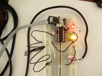
Oh, by the way- the garbled mess above is my LRC decoder. As I mentioned, LRC decoding works now. You may recognize the "instant MIDI" interface. The thin flatcable leads to the USBtinyISP programmer, and also provides power to the circuit. The LRC is on the bottom right of the picture, and its mono jack plug plugs into the circuit on the bottom left. As the above doesn't make much sense otherwise, here's the schematic:
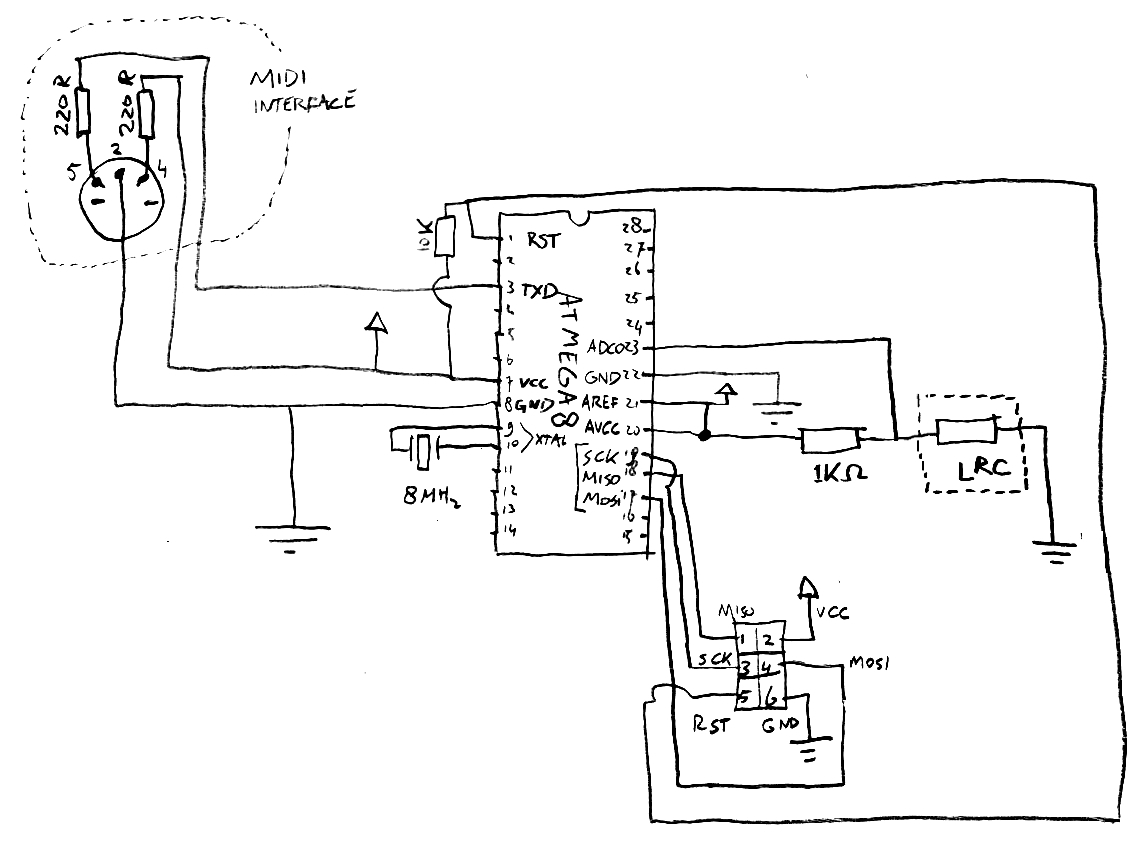
And the actual adc code, shamelessly stolen and adapted from another project:
unsigned int read_adc(unsigned char adc_number)
{
        unsigned char adlow, adhigh, counter;
        unsigned int adsum;

        // status for ADC: enable adc, start 1st conversion, free run,
        // clock prescaled with factor 64 ->57kHz clock with fq=3.686MHz
        ADCSR = 0xE6;

        // select ADC, i.e. switch the MUX to the selected ADC
        ADMUX = adc_number;

        // reset the averaging sum
        adsum = 0;
        int average=2;
        int maxcount=1<<average;
        for(counter=0; counter<maxcount; counter++ )
        {

                // wait N times 4.4ms in subroutine pause (here N=1)
                // for AD-conversion to be performed
                _delay_ms(4);

                // read adc-value (low byte must be read first !!!
                adlow  = ADCL;
                adhigh = ADCH;

                // add the read value to the averaging sum
                adsum += (adhigh<<8) + adlow;

        }

        // divide the averaging sum by the number of values
        adsum >>= average;

        return adsum;
}
The ADC code returns values which initially I sent out through MIDI.
As I've ripped off existing code, I'm not sure about the actual conversion
rate. I've made a few minor modifications though. First of all, the 'int average=2' means 2 to the power of 2 conversions in total will be made, the result of which will be averaged. This will help reduce sensitivity to noise. It worked all right, and allowed me to figure out which buttons would usually return which values. I then wrote code which would convert a button press to a value based on the nearest match. That is, if there would be ADC values 100, 110 and 120 for button 1, 2 and 3 respectively, then a value of 101 would be interpreted as button 1. Some debouncing code performs two button readings. If both read operations indicate the same button, it is assumed that that button is being pressed. Finally, depending on which button is being pressed, a MIDI message is being generated and sent out the usual way.
Being in the mood for quick results, I decided to send note on/off messages prior to doing actial MIDI MMC. I hooked up the MIDI interface of the computer to a softsynth, and could now abuse the LRC to play music (badly)!!!
Sunday 2009-11-28 - USART code fixed
I received a reply regarding the USART code. As it turns out, the example USART code in the ATmega8 documentation is wrong. It should have been:
void USART_Init()
{
/*Set baud rate */
UBRRH = 0;
UBRRL = 15;
UCSRB = (1<<RXEN)|(1<<TXEN);
/* Set frame format: */
UCSRC = (1<<URSEL)|(0<<UMSEL)|(0<<UPM0)|(0<<UPM1)|(0<<USBS)|(1<<UCSZ1)|(1<<UCSZ0)|(0<<UCPOL);
}
Apparently this was mentioned in the special sub-section of the ATmega8 datasheet USART section entitled "Accessing UBRRH/UCSRC Registers". In any case, I've rolled back my 'hack' and am now doing things right.
Saturday 2008-12-20 - Instant MIDI receiving interface
After having an instant MIDI send interface, I decided I'd like to have something similar for receiving MIDI as well. Here's the schematic that I used:
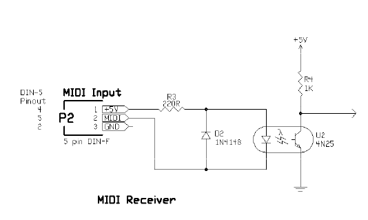
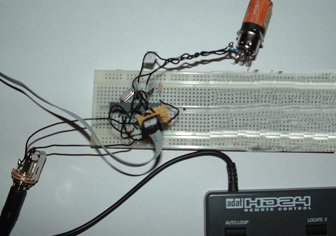
Nothing too fancy in there- the trickiest part is the 4N25 optocoupler, but it's readily available. So I soldered together this contraption:
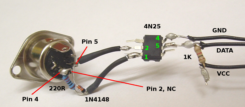
Note that pin 2 of the DIN plug is not connected. This is correct; it is part of the MIDI standard and intended to prevent hum by ground loops. The result isn't very pretty either, but it's intended for prototyping only.
To test the whole thing, I used the (known to work) instant MIDI sending interface and put together the tiniest bit of code to echo incoming MIDI data on the output:
#define F_CPU 8000000UL
unsigned int baud=15; // based on 8MHz clock

#include <avr/io.h>
#include <util/delay.h>

void USART_Init()
{
  /* Set baud rate */
  UBRRH = (unsigned char)(baud>>8);
  UBRRL = (unsigned char)baud;
  /* Enable transmitter and receiver */
  UCSRB = (1<<RXEN)|(1<<TXEN);
  /* Set frame format */
  UCSRC = (0<<UMSEL)|(0<<UPM0)|(0<<UPM1)|(0<<USBS)|(1<<UCSZ1)|(1<<UCSZ0)|(0<<
UCPOL);
}

void USART_Transmit( unsigned char data )
{
  /* Wait for empty transmit buffer */
  while ( !( UCSRA & (1<<UDRE)) )
       ;
  /* Put data into buffer, sends the data */
  UDR = data;
}

unsigned char USART_Receive( void )
{
    /* Wait for data to be received */
    while ( !(UCSRA & (1<<RXC)) ) ;
    /* Get and return received data from buffer */
    return UDR;
}

void init_io(void)
{
	//	PD0	pin 2	RXD
	//	PD1	pin 3	TXD
	DDRD = 0<<PD6 | 0<<PD5 | 0<<PD4 | 0<<PD3 | 0<<PD2 | 1<<PD1 | 0<<PD0;
	PORTD = 0;
}

int main(void)
{
    init_io();
    USART_Init();

    while (1)
    {
        USART_Transmit(USART_Receive());
    }
}
I then proceeded to run the first test. It worked straight away! Of course it's more elegant to use interrupt-driven code rather than to poll for data, but to simply test whether things were working this was good enough.
