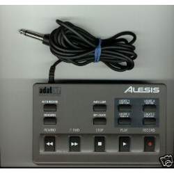
One of the goals I wanted to accomplish when picking up this electro stuff, was to find a way to hook up the Alesis LRC to my PC. For those of you who are not familiar with the LRC, it is the Little Remote Control that Alesis provides with their HD24 recorder (and pretty much all their previous 8-track digital tape recorders). It looks something like this:
The point of hooking up such a remote control to the PC, of course, is to permit using it to control DAW software. Specifically, in this case, I had in mind to use it with my HD24tools suite, but figured it would be even nicer to be able to use it with other DAW software as well.
One of the the first thing one notices when working with the LRC is that it has a mono jack plug. The reason that this is enough to control a multi-track recorder, is that the LRC is simply a resistor network. It is possible to simply measure its resistance values with a multimeter and get a reasonably accurate picture of what it does. As it turns out, it is also possible to use the play button in conjunction with the rewind, fast forward, stop and record buttons; this is useful for things like scrubbing.
Opening up the LRC reveals how it is wired up:
				 75
	PHONEPLUG  +-----------/\/\/\----------+-------+
	 tip       |             R2            |       |
	o----------+        _                  |       |
			  --+-- REHEARSE       |       |
	-----------+------o   o----------------+       \  52
	PL1        |   S5   _                          /  R1
		   |      --+-- AUTO LOOP              \
		   +------o   o------------------------+
		   |   S1                              \  52
		   |        _                          /  R3
		   |      --+-- LOOP END               \
		   +------o   o------------------------+
		   |   S4                              \  52
		   |        _                          /  R4
		   |      --+-- LOOP START             \
		   +------o   o------------------------+
		   |   S3                              \  52
		   |        _                          /  R5
		   |      --+-- LOCATE 0               \
		   +------o   o------------------------+
		   |   S2                              \  52
		   |        _                          /  R6
		   |      --+-- PUNCH IN               \
		   +------o   o------------------------+
		   |   S7                              \  52
		   |        _                          /  R7
		   |      --+-- PUNCH OUT              \
		   +------o   o------------------------+
		   |   S8                              \  52
		   |        _                          /  R8
		   |      --+-- SET LOCATE             \
		   +------o   o------------------------+
		   |   S6                              \  69
		   |        _         _                /  R9
		   | STOP --+--     --+-- PLAY         \
		   +------o   o--+--o   o--------------+
		   |   S11       |        S12          \
		   |             |                     /  510
		   |             |                     \  R10
		   |             +---------------------+
		   |                                   \ 100
		   |        _                          / R13
		   |      --+-- REWIND                 \
		   +------o   o------------------------+
		   |    S9                             \ 100
		   |        _                          / R11
		   |      --+-- F FWD                  \
		   +------o   o------------------------+
		   |   S10                             \ 100
		   |        _                          / R12
		   |      --+-- REC                    \
		   +------o   o------------------------+
		   |                                   |
		   |             100                   |
		   +------------/\/\/\-----------------+
				 R14

   Button          Calc.     Measured	PCB button name
--------------------------------------------------------
1  Rehearse 	75 ohm    (76)		S5 All input
2  Auto loop	127 ohm   (127)		S1 Auto input
3  Loop end	179 ohm   (178)		S4 Auto 2>1
4  loop start	231 ohm   (229)		S3 Locate 2
5  locate 0	283 ohm   (279)		S2 Locate 1
6  punch in	335 ohm   (330)		S7 Locate 0
7  punch out	387 ohm   (381)		S8 Auto play
8  set locate	439 ohm   (432)		S6 Set locate
9  stop+play	498 ohm   (500)         S11+S12
10 rewind+play	598 ohm   (600)         S9+S12
11 ffwd+play	698 ohm   (700)         S10+S12
12 rec+play	798 ohm   (800)         S13+S12
13 play		908 ohm	  (900)         S12
14 stop         1008 ohm  (1000)        S11
15 rewind	1108 ohm  (1100)        S9
16 ffwd		1208 ohm  (1200)        S10
17 rec		1308 ohm  (1300)        S13
18 all open	1408 ohm  (1400)        -
With that in mind, we now know everything there is to know about the device, so we can now focus on actually decoding it.
When I started on this project, the only microcontroller I had available was the ATtiny2313. I previously used this uC for MIDI, and this turned out to be easy to do due to the built-in USART. Unfortunately, the ATtiny2313 does not have an A/D converter, so I had to find another way to read the resistance values of the LRC. (My very first attempt, over two years earlier, failed miserably; simply hooking up the LRC instead of a potmeter of an analog USB joystick did not do the trick).
Naively, I came up with this schematic:
I was planning to measure the time it took to charge the capacitor, and use that value as estimate of the resistance being measured. After each time charging the capacitor, I'd "reset" it by shorting its two poles using a transistor as a switch. However, I wasn't sure how the analog comparator of the ATtiny2313 worked. I did try breadboarding something along this schematic, but my best effort didn't work. The readings were all over the place, and there was more noise than signal, possibly caused by the fact that the capacitor had to be ridicilously small. I'm not sure why I got so much noise, but my best guess so far is that the strips of the breadboard may have had sufficient capacitance o mess things up.
I considered using an ATtiny45, as it does have a built-in A/D converter- but noticed that it doesn't have a built-in USART. I figured an hour of my time was worth more than two pounds, so I ordered in a few ATmega8 controllers. As those have both ADC and USART built-in, they're a perfect match for this project.
In the meantime, someone on the electro forum suggested I hook up the analog remote control to the microcontroller using a pull-up resistor of about 1k to the VCC line. He included a spreadsheet showing the voltages that I'd be able to expect. Hey- suddenly the range seems more usable, as it goes from ~.35 volts to ~2.25 volts. What is more important- I get it, because the pull-up in combination with the LRC is simply a voltage divider. I looked for a more optimal pull-up value, but didn't find any. Either the range would be smaller, or the smallest ADC step. Currently, on an 8-bit ADC the measurements for different buttons would be as little as 5 values apart; this implies that a 6-bit ADC (which was the expected resolution of the capacitor-charging ADC) would, in fact, most likely not have been accurate enough.
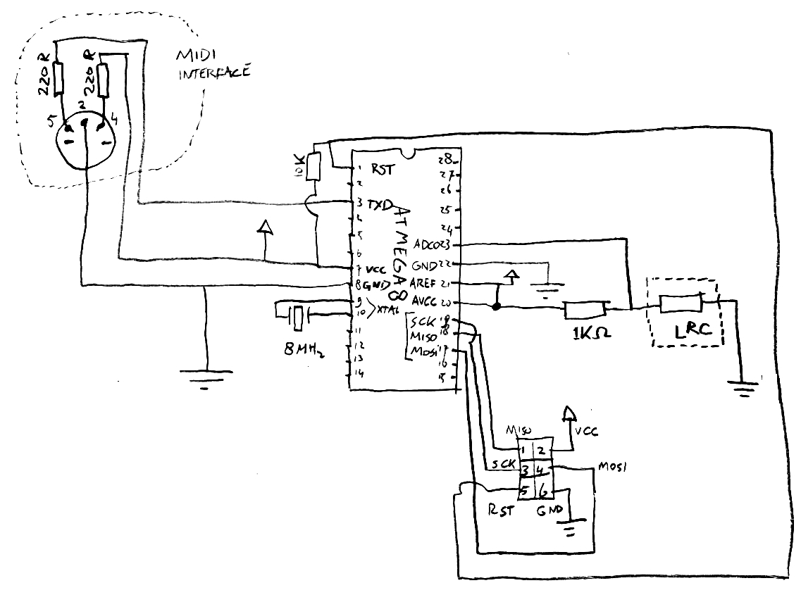
But how to hook it up? This seemed a bit confusing at first. Studying a few ADC schematics revealed that some people would hook up a potmeter with its center pin hooked up to the ADC and the other two pins to VCC/GND. In effect, the potmeter also works as a voltage divider; so all I had to do was hook up one side of the 1k resistor to a 5V source, one side of the LRC to ground, and the place where they join to the ADC pin.
So I came up with this schematic:
The ADC code was lifted from an existing project and adjusted for my needs:
unsigned int read_adc(unsigned char adc_number)
{
        unsigned char adlow, adhigh, counter;
        unsigned int adsum;

        // status for ADC: enable adc, start 1st conversion, free run,
        // clock prescaled with factor 64 ->57kHz clock with fq=3.686MHz
        ADCSR = 0xE6;

        // select ADC, i.e. switch the MUX to the selected ADC
        ADMUX = adc_number;

        // reset the averaging sum
        adsum = 0;
        int average=2;
        int maxcount=1<<average;
        for(counter=0; counter<maxcount; counter++ )
        {

                // wait N times 4.4ms in subroutine pause (here N=1)
                // for AD-conversion to be performed
                _delay_ms(4);

                // read adc-value (low byte must be read first !!!
                adlow  = ADCL;
                adhigh = ADCH;

                // add the read value to the averaging sum
                adsum += (adhigh<<8) + adlow;

        }

        // divide the averaging sum by the number of values
        adsum >>= average;

        return adsum;
}
Now that I could read the ADC, how would I know which buttons would return which values? Simple- I'd just communicate the actual values over the MIDI port. After that, I set up a data table with the values as measured for each button. Only thing is, as I found out, the USART code from the data sheet of the ATmega8 didn't work. After asking around, here is what the USART initialisation code should have looked like:
void USART_Init()
{
/*Set baud rate */
UBRRH = 0;
UBRRL = 15;
UCSRB = (1<<RXEN)|(1<<TXEN);
/* Set frame format: */
UCSRC = (1<<URSEL)|(0<<UMSEL)|(0<<UPM0)|(0<<UPM1)|(0<<USBS)|(1<<UCSZ1)|(1<<UCSZ0)|(0<<UCPOL);
}
Now that I had all building blocks complete, I could read the buttons, create MIDI messages and send out those MIDI messages. Perfect - I could now control any DAW, as well as the HD24 recorder, directly from my LRC decoder box. Right? Wrong. Due to the fact that the LRC itself has no intelligence built-in whatsoever, a box that only decodes the LRC is very limited. The HD24 does not implement MMC messages for FFWD or REW, and anything that uses locate points (just about every button on the LRC!) requires the controlling device to know what those locate points are set to. I could implement PLAY, REC and STOP, but little more. Was all my effort... USELESS??