How to repair your LCD backlight
1. Introduction
Today's LCD displays are magnificent devices: thin, bright display, wide
viewing angle, light, low power consumption, high resolution. There's one
drawback, however: after several years of extensive use, the backlight
wears out and eventually dies. "Several years" is really really a short
lifetime compared to cathode based monitors (you know, the heavy power
hungry thing sitting on your desk).
You can imagine my frustration when the display of my not-so-brandnew-but-still-not-very-old-either
notebook (2 1/2 years) suddenly dimmed to an unreadable level, except at night with all
curtains closed. No these are not my regular working hours (anymore).
Since it's a waste to throw away a notebook in perfectly working order (no bad sectors
or anything) I decided to repair it myself. A bit of an adventure since I'm
unfamiliar with LCD/TFT
technology, but since we have the World Wide Web the word "unfamiliar technology"
has lost its meaning.
2. LCD Backlighting technology
There are two ways to backlight an LCD display: using electro-luminescent foils, and
using Cold-Cathode Fluorescent Tubes (CCFT's). The first type are thin foils that light up in the
dark. Neat stuff, but primarily used for small (monochrome) hand-held devices. The second
type, CCFT's, are used in notebooks. Cold Cathode Fluorescent Tubes are similar to TL tubes
(the long tubes in the ceiling of your average office building): a long glass tube filled
with a gas of some kind, and with electrodes on both sides. Explaining how this all works
is a bit beyond the scope of this page, but basically a discharge takes place so that the
gas is ionized and lights up. In a display, the light produced by the tube is heterogeneously
distributed over the display by several layers of foils, including a semi-translucent mirror
foil placed behind the actual LCD screen. Quite ingenious.
So, the basic components of a backlight display are a device to produce a high voltage,
called an "inverter", and the CCFT tube itself. If your backlight is broken, then there
are two possible causes: (1) your inverter broke down or (2) your tube has worn out.
It is usually located in the LCD screen itself, because the wires to the CCFT tube should
not be too long, and carry a high voltage. So they should be confined inside the display
casing to minimize the risk of wire exposure.
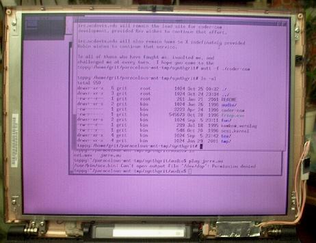
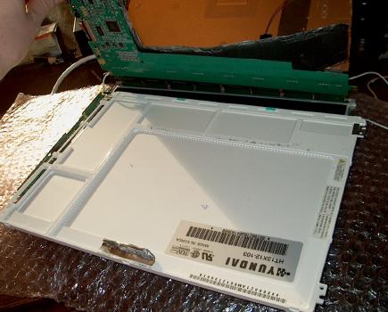
In the picture below you can see
that in my notebook, it is located at the right below the LCD screen. To the right of the
screen, you can see the wires towards the tube (my CCFT tube had lost
almost all of its light, and had become a bit purplish).
The inverter itself is often wrapped in
aluminium foil or placed in a metal casing to reduce interference. Two components make
it easy to recognize: there's always a coil on it, and a transformer. See this closeup
of the inverter in my notebook after having peeled the aluminium foil off:
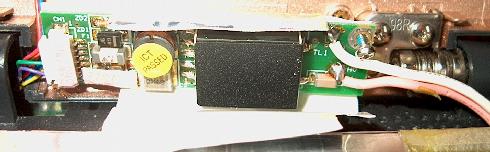
The CCFT tube is usually built into the LCD panel itself, so it cannot be seen in this
picture.
3. Fault diagnosis
How to know where the fault is? In my case, the problem was that the tube did still
produce some light, but just not sufficient. So I suspected a problem in the inverter,
and in particular the brightness control part. CCFT brightness control is achieved
using Pulse Width Modulation with a low frequency pulse (in the order of 100Hz). The duty cycle
then determines the brightness. However, the problem with modern inverters is that they
are all built up using SMD technology; see the back side of my notebook's inverter below
(surprise!):
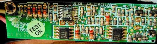
This circuitry generates the brightness pulse, which is then modulated onto a high
voltage resonant oscillator. "Resonant" here means that the frequency of the high
voltage pulses that the inverter generates is adapted to the tube that's connected to it
using a feedback loop. This makes the inverters quite generic, which is good news if you
have a broken one: they can be easily replaced by one of a different type.
Well back to the fault diagnosis: attach two needles to the testpins of your
multimeter and try to discover if your inverter is still generating its pulses,
or exchange it for another one and see if it helps.
In my case, it didn't: I purchased a new inverter at DIL electronics in Rotterdam (www.dil.nl),
and connected it to the wires leading to the CCFT tube. Switched on the notebook and...
hurray, the CCFT lighted up! But boohooh, same low-intensity level. Conclusion: the inverter
was not the problem, and instead the CCFT
had to be replaced. Luckily, I also ordered a new CCFT tube with the inverter, initally
"just to play with" (for a total of about 15 Euro). These kits are often sold to "case modders",
people (often gamers) that put the saw into their PC case to make holes, and then build
coloured CCFT tubes in them to make them look nicer.
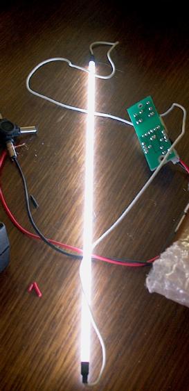
To check if this endeavour had any chance of being succesful, I first checked if the new
CCFT tube would operate with the notebook's inverter, and if sufficient light would be
produced. So I disconnected the wires from the inverter to the LCD panel, and connected
them to the new CCFT tube... switched on the notebook... and hurray, light! So onto the
tube replacement adventure.
4. Replacing the CCFT
The LCD panel itself (a Hyundai HT13X12) looks like a module that doesn't want to be taken apart.
To find out where the CCFT is, just follow the wires leading from the inverter to the panel.
In my case, the wires just disappeared into a large white plastic frame. There seemed to be
no way to replace the CCFT without taking the entire panel apart. So that's what had to be done...
I first peeled off aluminium foil from the places where it seemed to obstruct a proper
disassembly of the panel. Then unscrewed all the screws I could find, and after several attempts
succeeded in opening the panel:
The green thing is the circuit board. It connects to a plastic foil carrying hundreds of
delicate conductive traces, leading into the bottom half. Be very careful not to bend or
damage this foil! It's the same type of conductive trace-on-plastic that's used in your old ZX Spectrum
keyboard, or microwave keyboards. If you bend it too much, the trace crackles and doesn't conduct
no more. Bye bye LCD screen.
The white half contains the LCD itself, the mirror layers, and the CCFT tube. The mirror layers and
the CCFT tube could be easily taken from the LCD/circuitry part. On the picture below, you can
see the pink wires leading towards the CCFT tube.
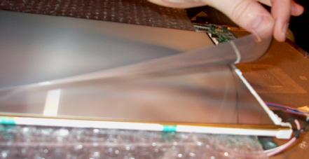
You can also see me lifting a layer from the mirror assembly. It's better that you don't. Any
dust particle will become an annoying speck on your screen... so leave all layers where they are,
and make sure no dust, wires, hairs, or any other materials can creep between them.
In my case, the CCFT could (after some convincing words) be removed from the "mirror assembly".
Unfortunately it was much thinner than the CCFT
I bought... and it was wrapped in a metal U shape to reflect as much light as possible into
the mirror assembly, and probably also to shield it off to reduce interference. By making
some mechanical modifications to the plastic frame, the new CCFT would fit into the assembly.
There was no room for the metal U frame, so I cut a (much thinner) reflective layer using
household aluminium foil. The foil was fixed with very small pieces of cellotape (even smaller
than the one shown in the picture).
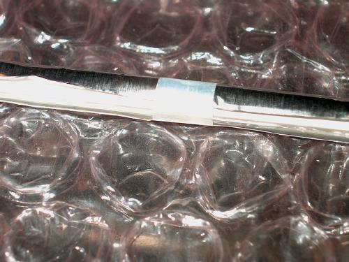
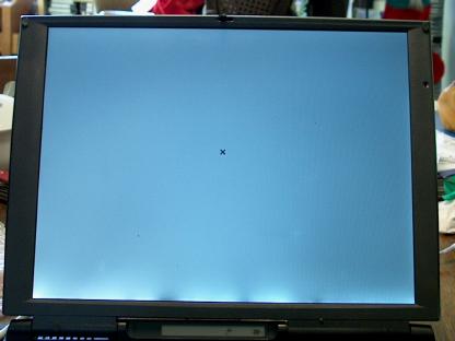
If you too are going to have to use aluminium foil as
a reflective layer, cut it as straight as possible. Any irregularities will show up as
light or dark spots on your LCD screen afterwards (see picture). If your tube is very light, you could
even consider not to use a reflective foil at all.
The tube was then placed into the mirror assembly with the opening directed into the mirror
layers. The assembly was fitted again into the circuitboard / LCD screen combination, and
all screws were refitted. The notebook was switched on, and behold... there was light!
Sufficient light! But not a proper bootup screen, duh. Did I break a delicate metal trace?
Too much static electricity? Fortunately not. It turned out that there was a tiny
connector on the circuit board that fitted into a connector on the LCD screen. These connectors
only make proper contact if all screws are tightened properly. So beware of this when
reassembling your panel. Also, refit all aluminium foils or other metal layers. Without them,
you will get annoying interferences on your screen.
5. Project succesful!
I am now the happy owner of a notebook with a revived screen. There are some dark and light
spots on them due to uneven reflection of light in the aluminium foil, maybe I'll
correct this some day. For all current LCD monitor and notebook owners, I hope their
tube lasts longer than mine. If not, then I hope this page can help you to replace
the backlight tube in your screen. If so, then you could maybe be so nice as to drop
me a line on grit@wwcn.org. I'm very curious to
your backlight repair adventures!
Grit